woodbowlsandthings

January 29, 2018

Hollowing Rig

Filed under: Tools, Wood Lathe — Tags: , , , , , , , — peteblair @ 3:33 pm

For a couple of reasons I have spent a few hours over the last little while making my own Jamieson style Hollowing rig.
One reason is because I just like to make stuff and another is because I wanted to see if this style of hollower would be easier to set up and provide more tactile feel when I hollow small vessels.
I am lucky in that I have a Kobra Hollowing System and find it great when hollowing larger forms but sort of clunky and overkill on small forms.
I also am the sort of person who has never liked to do anything twice if I could avoid it and so wanted too be able to utilize some parts from the Kobra and anything else I already have on hand.
I did test it today and found it easy to use but possibly not as easy to set up as I had hoped.
OK, here we go. I first decided that I needed to make only the two major components (the frame and arm) and as I said, I wanted to be able to adapt what I already have in the shop where possible.


I planned to use existing cutters and cutter holders and now know I want to utilize the laser and camera I already have as well as the tool post support from my Oneway Easy Core jig and the tool support from the Kobra.


I hunted around the shop to see what sort of material I had on hand that I could use. I found a three foot piece of 1/2″ steel rod and also a three foot piece os 1 x 1 x 1/8 angle iron. These two pieces should fit the bill.

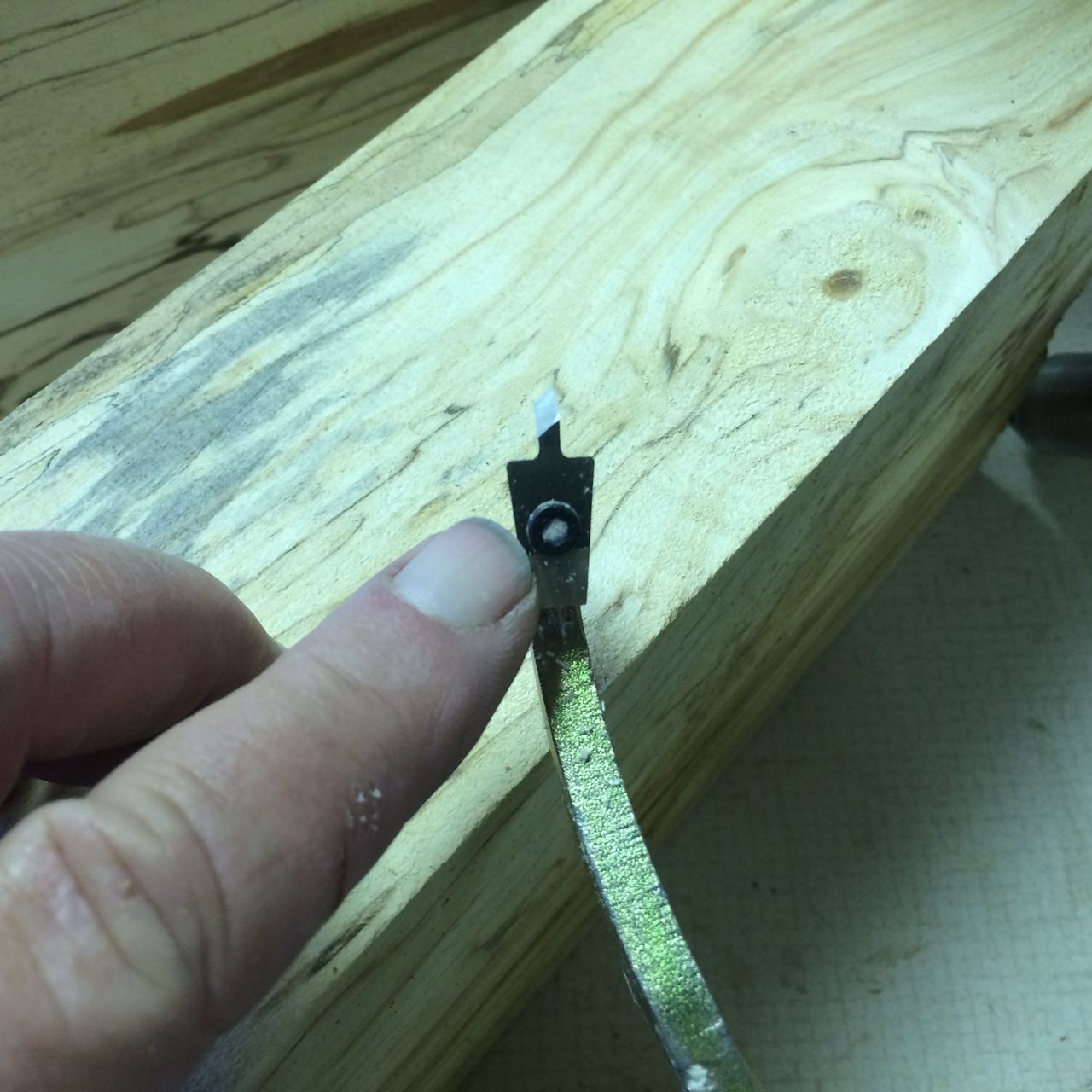
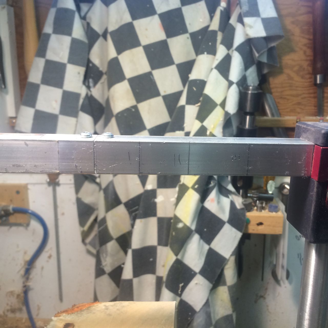
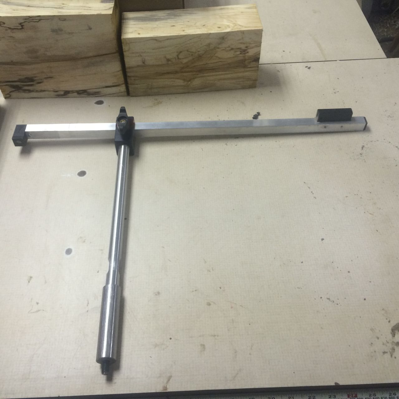
My first dilemma was to decide if I should cut and weld the tool holder arm or just bend it. I know of others who welded theirs but thought what the heck I have a small torch with Mapp gas which I felt would do the job. I marked the 1/2″ rod to allow me to produce three bends and have a little stub left for attaching the tools holders to. Oh, by the way, the tool holders I am using were made for my Kobra by a good friend but because they are designed for smaller cutters I seldom used them. I had to drill a 1/2″ hole in each of the four different size ones to allow me to hold 1/4″, 5/16″,3/8″ and 1/2″. After drilling the hole I also needed to drill and tap two holes in each to allow me to  fasten these to the tool holding section.

I think I may have just been lucky when I heated and bent the three bends I did the bends only by eye and they came out flat and the final bend actually came out just about exactly the right length. I drilled a hole through the rod and into the end of the bent section and tapped in a ‘1/8″ Roll Pin.

Next to make the support stabilizer. Again I was lucky enough to find a section of 1″ diameter solid steel about the correct length. I cut a notch in one end about 1/2 way through and about 1″ deep.I had planned to bolt the bottom section of angle into this notch but changed my mind and got help from a friend to weld it instead. Glad I did this as it is much much more solid. The bottom was drilled and tapped to take a 3/8″ grub screw. I need to do this I think because when I change sizes of cutters I also have to change the height of the holder to ensure I am cutting on or just below center.

Next I needed spacers that were just slightly longer than 1/2″. Here my small metal lathe really came in handy. I was able to chuck up a couple of short pieces of 1/2 tool steel and precisely make the length I wanted. Because I am not planning to do any larger work with this tool I wanted the two parts to slide easily inside one another.

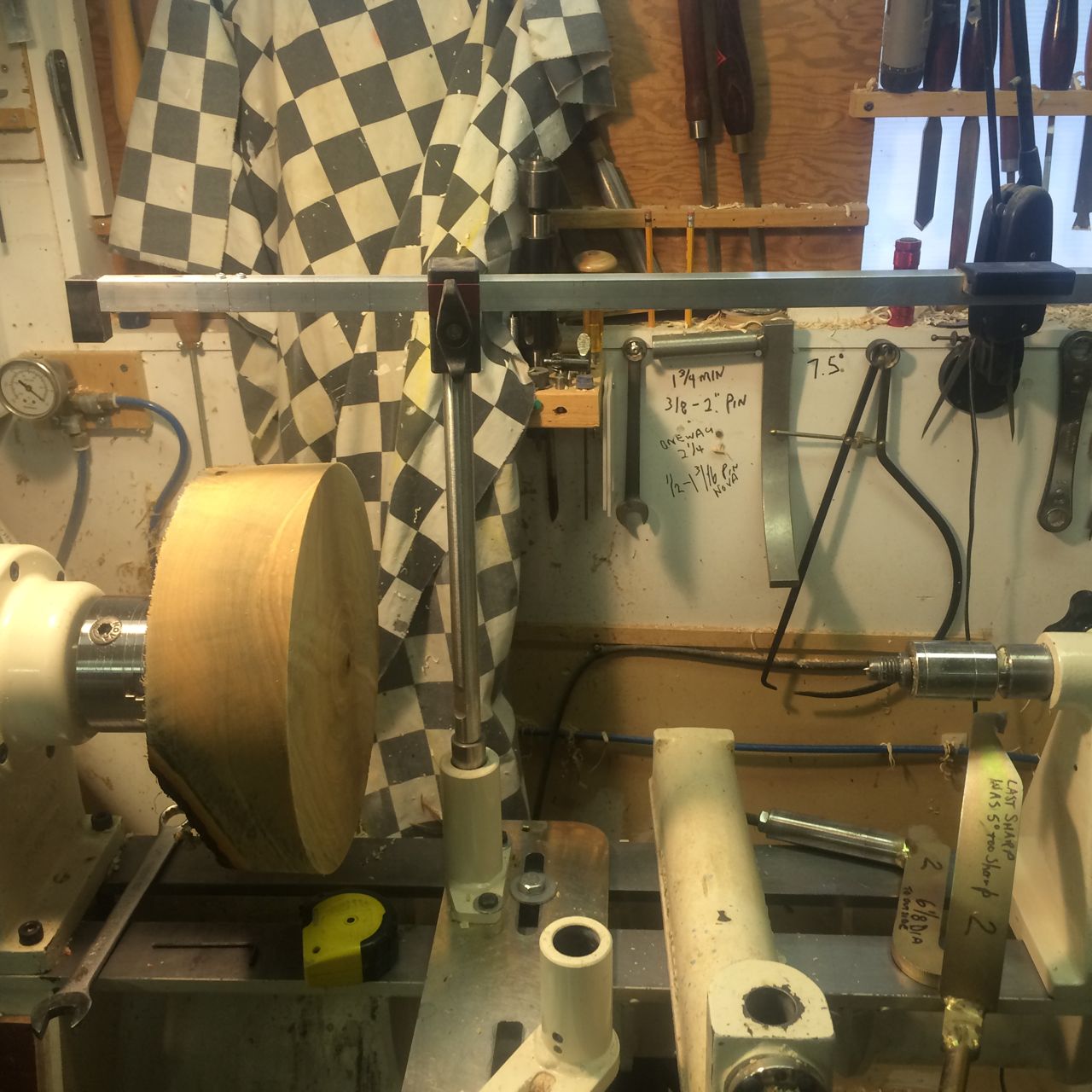
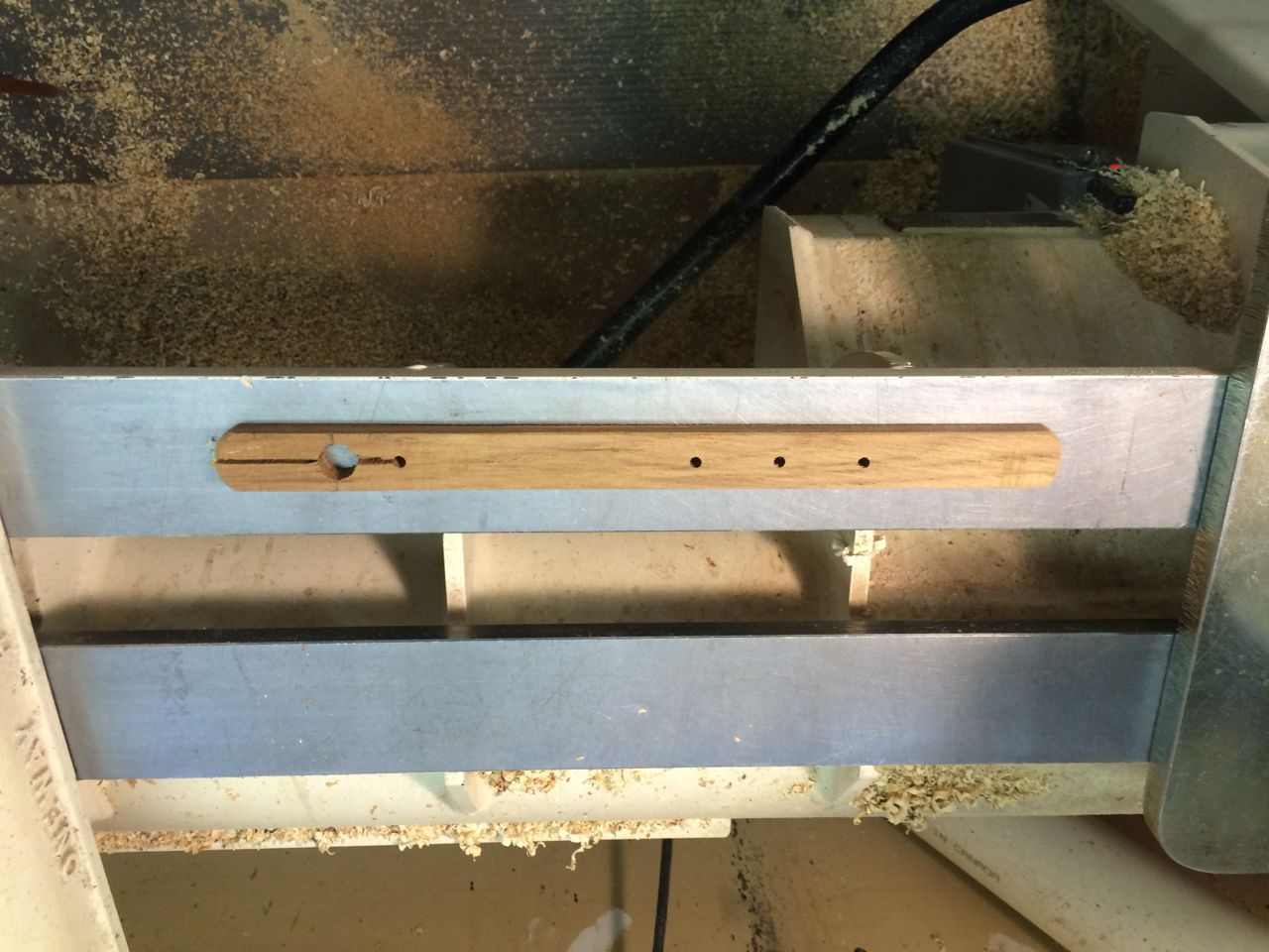
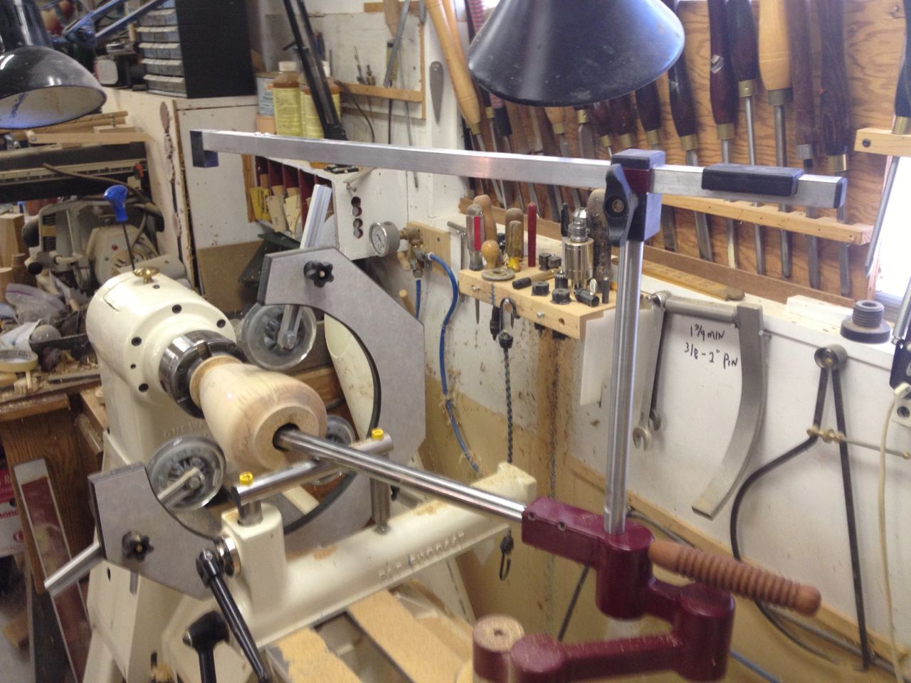
After bolting the angle together with 1/4″ bolts and lock washer with my prepared spacers in between it was time to test the rig. Today I chucked up a small piece of Gravenstien Apple and began the test. I want to be able to work through a small as possible. This means that I can use 1/4″ tools through a 1/2″ hole but even at this the tool does drag a little on the bottom of the opening. I believer the ideal size of opening should be just larger than twice the diameter of the cutter bar.

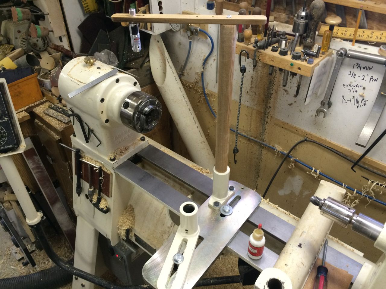
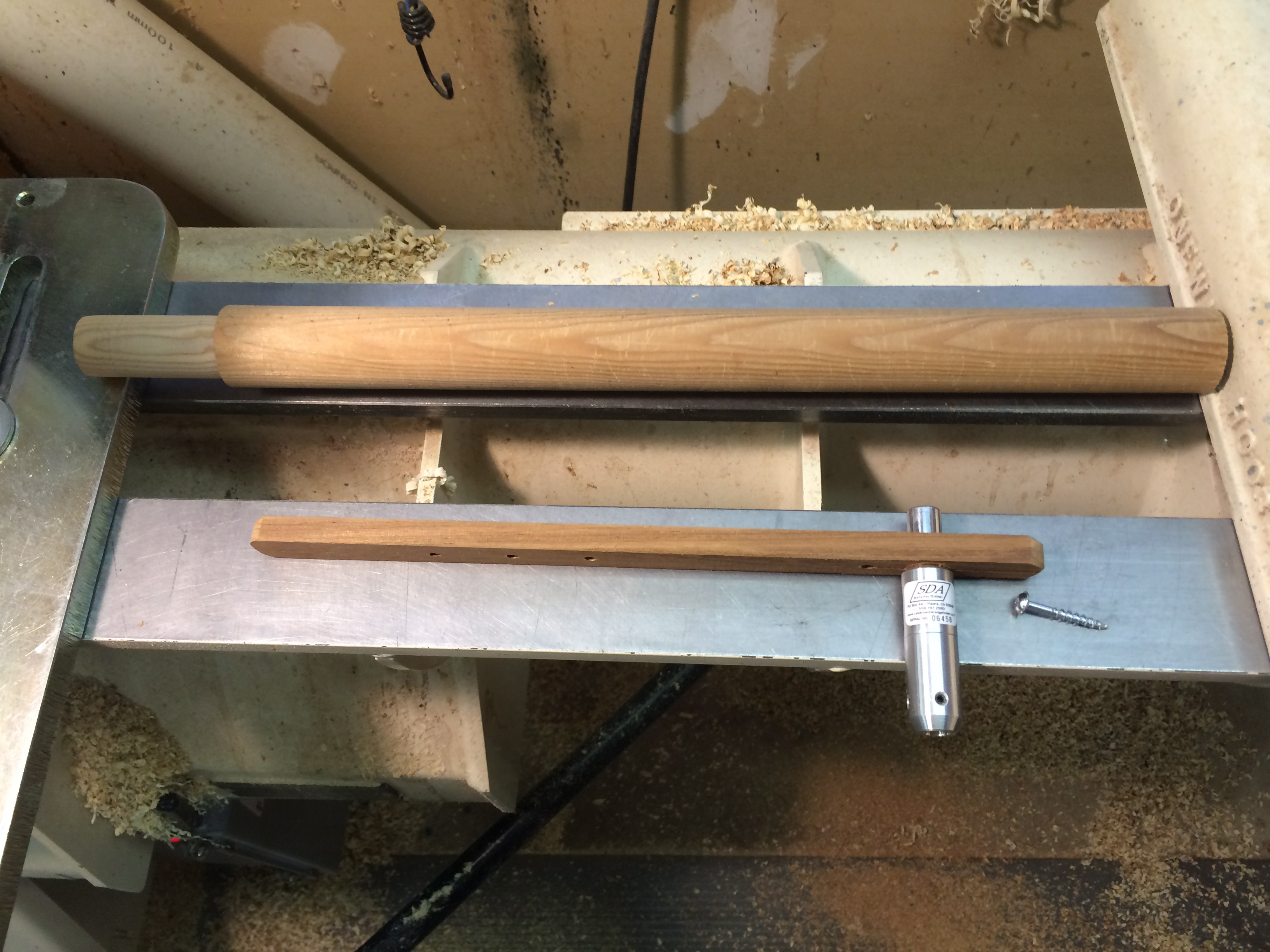
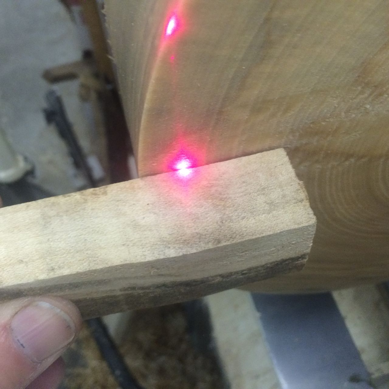
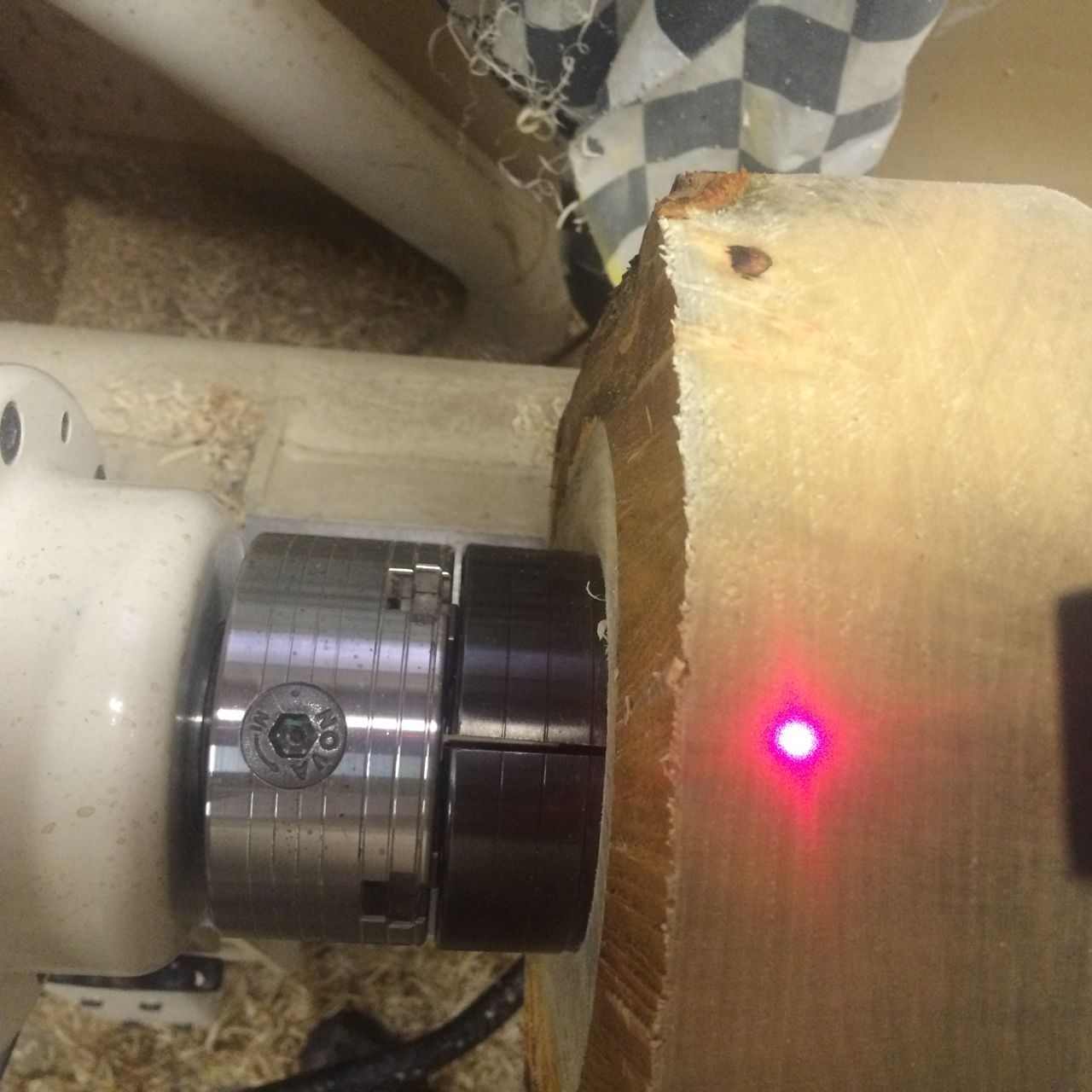
It worked really good but I soon realized that the continual stopping to test wall thickness and starting again was as pain and I needed to add either or both my laser and camera set up. To allow this I found in my stock a 3/8″ joiner nut which I cut in half then faced off with my metal lathe. I took it to the local Machine shop and paid the grand sum of $5.00 ( no receipt of course) for them to weld it to my rig. This is the same thread as is on the post that holds my laser and video camera.

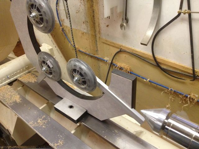
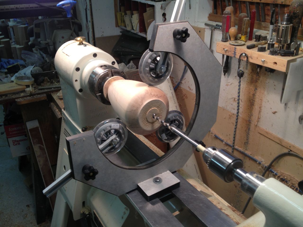
Here’s what the setup looks like from a couple of angles and then with the laser and camera. It does appear overkill but you know what? I don’t care. I may make a new shorter support bar to get the laser and camera closer but for now I think I can work with it just fine.

November 11, 2017

Video Hollowing

Filed under: Wood Lathe — Tags: , , , , , , , , , , — peteblair @ 4:03 pm

I know that there are lots of turners who are either already hollowing using video of are thinking about trying this technique. This Blog is meant to be a jumping off spot for those who are still contemplating the process. It’s only the way I do it and not by any means a difinitive way to proceed. I do not plan to share the details of the equipment I use because there are so many choices and I purchased so many years ago the items may no longer be available.

As far as I can remember, the use of video in hollowing became known about 5 years ago when a world renown turner began demo’ing and selling his system.

For those of you how have been living in a cave or on another planet for the past 5 years the technique involves positioning a camera above the cutter and then drawing it’s outline on a sheet of mylar which then appears on the video screen when the cutter is actually in the form. I hope I have explained it well enough but please feel free to contact me should I be able to add anything or help you better understand the technique.

So about 5 years ago and being the cheap SOB that I am, I thought I could hack together my own system. I had an old MS laptop laying around and I had WIFI phones and cameras with the ability to connect to it, but, of course that wasn’t enough for me. I soon was scouring Amazon for cameras etc. I found a very cheap, new I was told, Colonoscope camera. I sure hope it was new!! It had it’s own light but the picture was a problem.
Anyway, to cut a long story a little shorter, I found that the Lap top was a pain to set up and take down and by the time I ran the software to get everything working I could have hollowed several vessels using my laser. In addition, the web WIFI cams all had a short ‘lag’ which drove me nuts!!  This led me to stop trying the process and continue my old ways using a laser.

I hadn’t totally given up though as I discovered that several turners were using Back-Up Automobile camera set-ups which included a small monitor and camera. Yep, a few were even shown with the lines to back between which I apparently were pretty easy to ignore when hollowing.
So of course, I had to try those as well and also found a really cheap video surveillance camera without the monitor and bought that too.

When the part arrived I took a quick look and with all the wires etc. it all seemed way too involved. I’d just rather be turning than messing with all those wires!!

It might be my age or ?? but I have a great deal of trouble remembering peoples names and the turner who demonstrated his video techniques at the last meeting of the Vancouver and District Wood Turners Guild has fallen into that category.
It’s too bad because it was his demo that got me thinking a little more about utilizing this technique.

So the next day I hunted around my shop, it took me about 2 hours to remember that I had stashed all the parts in an old sewing box.

The only easy to hook up was the surveillance camera because it came with a 12 volt brick power supply. The back-up-system was designed to wire directly to the 12 volt of a vehicle. Lucky for me I have ‘bricks’ of all voltages and designs in boxes and drawers. I found a 12 volt one, cut the cord and wired it to the back-up system and hooked up the surveillance camera and quickly discovered that the distortion was way too much at close range to be usable.

So with wires going every which way I connected the complete back up system. Dragged it over to my lathe and with a few minor modification had it up and running in no time. It worked great but the back up monitor is only about a 7″ screen. I need something bigger.

I remember that we moved a cable box from a 17″ tv in our kitchen to a room where one of our grandsons ‘hangs’ so he could use it on a large tv that his dad has left for us to store. My wife was quite happy to have it out of the cabinet that it was in now she has more shelf space to display her ‘stuff’.

Ok, so now I am really on to something. I quickly disassembled the foot that the tv stood on and made an aluminum plate from which I could hang it on my exhaust fan box right at the end of my lathe. With a few quick changes it was up and running perfectly.

As you can see from the photos I hold mylar film on the tv with magnets and draw the outline of my tool on it with a sharpie. One cool thing about using the magnets as opposed to tape or ?? is that I can easily reposition it  should I change the angle of the cutter. In addition I can keep all the old sheets to reuse anytime I am using this system and thus don’t need to keep redrawing the cutter. If I like I could actually leave the TV in place but I need to come up with some sort of cover to keep the dust out so for now I stash it on a shelf. The camera and arm it is attached to simply hang on the wall behind my lathe. The camera does have a small lens cover. I’m not totally convinced that the camera is totally suitable and I continue to search for a cheap replacement. What I believe would work even better is what is termed a ‘closed circuit’ camera.

A couple of ideas that were shared at our last meeting that are exceptionally helpful are to place a white or black piece under the turning to provide contrast at the edge which helps to see where the cutter is. Another is if a round magnet is placed on the screen over the cutter and extending outward it provides a means to ensure the finished thickness is easily delineated.

Here are a couple of screen shots of the round magnet and how it makes it much easier to maintain the finished thickness.

There is one caution I would like too add. Not all cameras and monitors will provide a real time accurate dimension on the screen. The way to be sure you get the thickness you want is to aim your camera at a ruler and then measure the image on the screen to be sure you are getting a one-to-one. Mine is not but it makes no difference to me because once I set the thickness I want with the washer then I just use the edge of it as the guide.

March 6, 2016

Oneway Easy Core Laser aid

I have and love my Oneway Easy Core System. Before I purchased it I watched a video on the Oneway website which really got me going in the right direction and help me decide this was the coring system I wanted.
In the video were instructions to make several spacers that enable the user to position the cutter appropriately for whichever set of knives were being used.
I made dutifully made the spacers

IMG_2228and labeled them although they worked as advertized they never really worked as well has I had hoped, primarily because I often use different chucks and sometimes want to position the cutters off center.

Whenever I would use a different chuck or a different location for the cutter I was mostly guessing what the core would look like and exactly how thick the bottom would be.

At first I would position the system where I thought it should be and by holding the cutter over top of my wood, sort of swing it back and forth and look down from the top to try to guess what I would wind up with.

Next I made a pointed stick with a metal rod attached that I could position over the cutter and adjust it for each size of cutter. This actually gave me a better idea of where the cutter would cut, but still not quite what I was looking for.

I soon realized that I wanted a better ‘mouse trap” and realizing that I could easily adapt the laser from my Kobra Hollower to accurately position the cutter without the concern that I might cut too thin a bottom or even go through and hit my chuck.

Here is a photo of the set-up I am now using, it’s fantastic! Quick to set-up and adjust no matter which size cutter I’m using or how I have the blank mounted.

IMG_2198

I simply measured from the center of the pivot to the outside edge of the cutter and scribed these distances on the arm of my Laser. I have the three smallest cutters. Measured from the center of the pivot to the outside edge of the cutter they measure 5″ – 6 1/8″ – and 7 7/16″.

IMG_2218

IMG_2197

I am lucky that I use a 1″ threaded bar to adjust a router table when I use it on my oneway and was able to utilize it on the end of my Kobra Laser.

IMG_2210

While taking these photos I thought why don’t I also do a mock-up that could be utilized  by turners who either don’t have the same laser set-up I do or don’t already have a laser.

Here is a similar design that anyone with the Onway Coring System can easily make and use to take all the guess work out of the process.

IMG_2227

If you decide to make this tool, don’t forget to make the upright long enough for the biggest bowl that you can turn on your lathe.

Here are the components. First the bar to hold the laser and enable it to be adjusted for each cutter. I left mine a little long just in case I ever get a larger lathe. I drilled a hole for my laser a little smaller than it’s diameter, cut a slot with a hole at the end to allow the bar to open and gently pinch the laser. I then drilled holes for a screw to allow for the adjustment for each cutter as described above.

IMG_2224

These are all the components. I suggest that if you are following this design you fill the hole in the end of the upright with superglue to strengthen it(don’t insert the screw until the glue has hardened the wood around the hole). This will allow you to use it many times without stripping the screw hole.

IMG_2225In use, both designs work wonderfully. Here are a few photos of them in action.

One other major advantage of this design is that if a blank has bark or a natural edge it is easy to see exactly where the cutter will cut relative to that.

IMG_2208IMG_2209

December 22, 2012

LATHE STEADY

Hi all. A couple of weeks ago I decided I really needed a Steady for my hollow forms.

I searched the internet and asked on several forums if anyone had any good ideas about making a “C” style steady that will allow a laser to travel the full length of the form with no wheels or framework in the way.

I must admit I was more than a little surprised when I only got a few interested parties making suggestions. At that point I did some soul searching thinking that maybe my idea was without merit.

After spending more time with my Kobra hollowing system and thinking a little more about this project I decided that it was what I wanted even though it seemed that I was one of only a few who was interested.

I was pretty lucky as I had some 3/4″ solid phenolic that I was planning to use and I had some “T” track which I also had planned to use.

I drew a 16″ circle cause my lathe has an 8″ swing and then drew another smaller circle 1 1/2″ inside that.

Then I used a portable jig saw and cut out the centre.

Next I laid out the notches for the “T” track. I cut them 1/4″ deep and drilled holes for the Tee bolts

Next I cut the opening for the “C” shape and knocked off the corners of the C.

I notched another piece of the phenolic and drilled and tapped it to the bottom of the C

I then cut another piece of the phenolic and notched it to fit into the space under and between the ways of my lathe.

I found some nice rubber wheels at Lee Valley and bolted them to the ends of the T track.

Mounted it to my lathe and Walla!!

That’s about it. It works great!

BUT there are two changes I would make if I was to do it again.

1. I would cut the slots for the T track on the tail stock side of the steady

2. I would make the piece that attaches to the ways only on one side, the head stock side.

Both these changes would allow me to position the steady closer to the opening thus providing more support.

IMG_1375

IMG_1336 IMG_1339

Blog at WordPress.com.